Published on 2024-02-01 by avile040
Following the success of integrating the Champ motion control algorithm into the Red Dog quadruped, the next step was building a strong enough brushless design to overcome the difficulties of the previous designs of having lower torque. To meet this end a possible design was sought after to get the most torque out of an actuator while also moving fast enough for the robot.
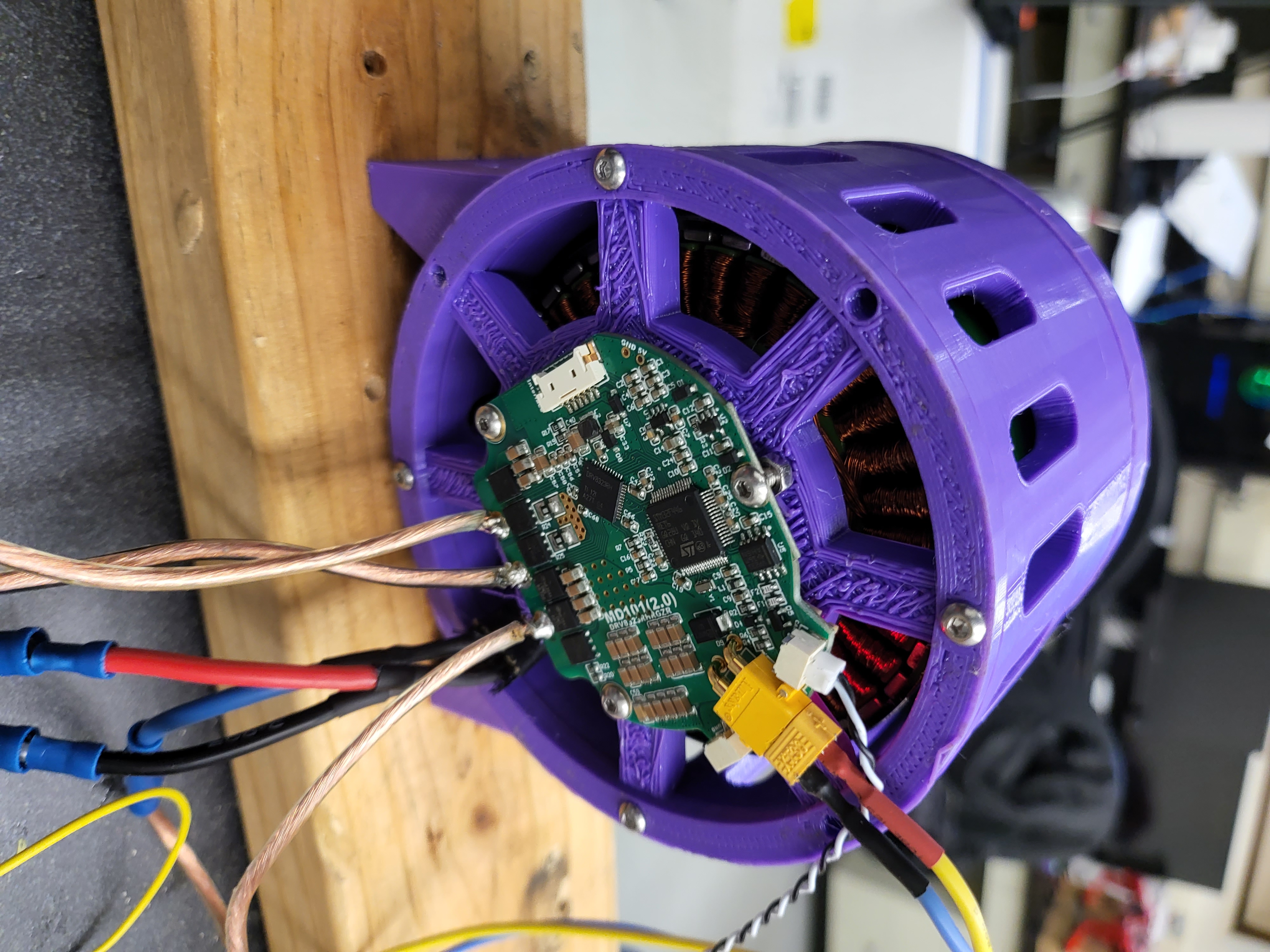
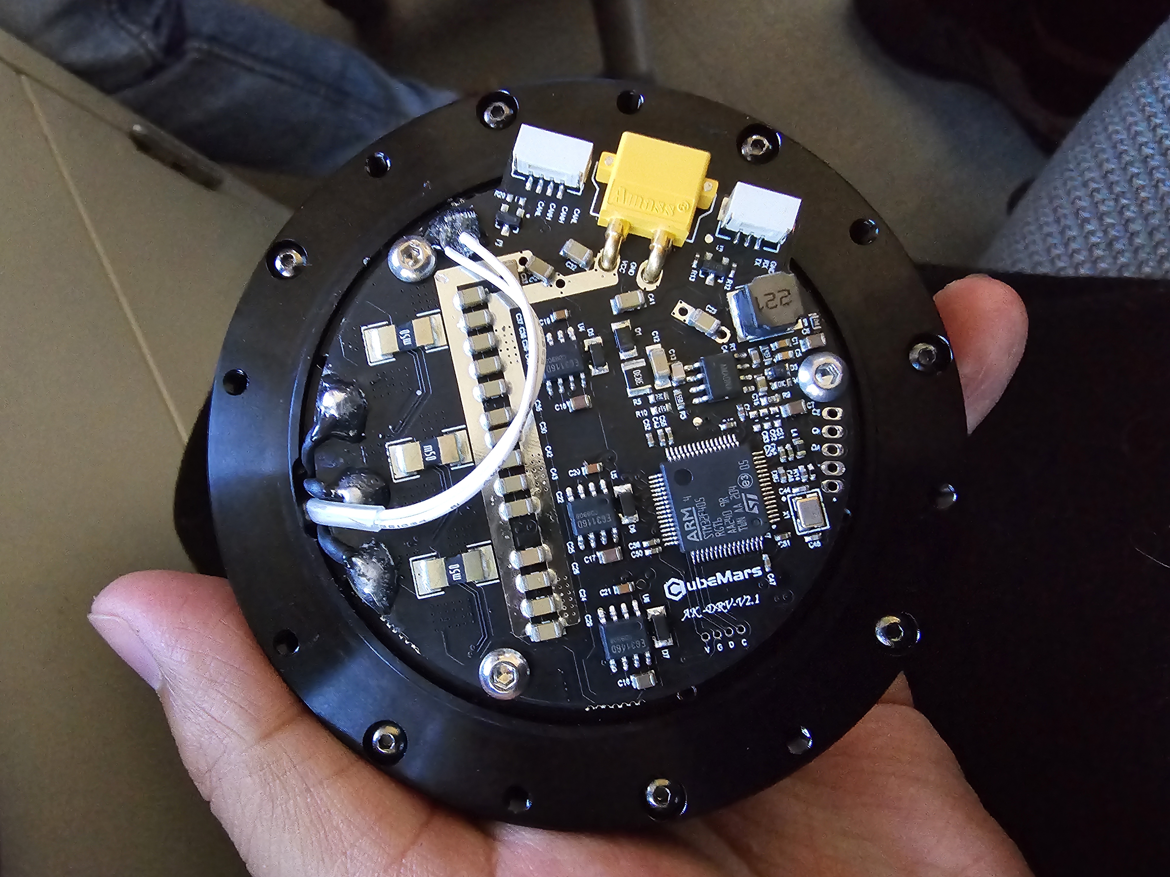
The controller board must also be fast enough and reliable to send and receive commands to translate commands while also being able to properly identify each motor with its own motor ID. With all of these requirements in mind, the closest board was the developed board from MIT mini Cheetah developed by Ben Katz which uses an STM32 as its main processor.

The brushless motors by themselves do not have enough torque for moving a heavy robot thus a gearbox must be built to satisfy the requirements. A 3D-printed actuator named OpenTorque Actuator from G-Levine was created and tested its performance with our current donated motors from T-motors U8.

The results from such tests determined that they were able to properly transmit the torque. The results below show the amount of torque that they generated using a scale to determine the amount of weight force produced by the motors themselves and with the actuator. These results were then compared to find the difference in the loss of torque when using the gearbox.
8:1
| Motors alone torque(Nm) (weight g/1000*9.8*0.16) | Calculated (Torque*8) | 8:1 Actuator gearbox Torque(Nm) | Difference(Actual-Calculated) |
|---|---|---|---|
| 0.186592 | 1.492736 | 2.160704 | 0.667968 |
| 0.387296 | 3.098368 | 3.23008 | 0.131712 |
| 0.592704 | 4.741632 | 4.95488 | 0.213248 |
| 0.801248 | 6.409984 | 6.599712 | 0.189728 |
| 1.008224 | 8.065792 | 8.010912 | -0.05488 |
| 1.226176 | 9.809408 | 9.7608 | -0.048608 |
| 1.423744 | 11.389952 | 11.819584 | 0.429632 |
| 1.649536 | 13.196288 | 13.387584 | 0.191296 |
| 1.83456 | 14.67648 | 14.95872 | 0.28224 |
| 2.025856 | 16.206848 | 16.80896 | 0.602112 |
A modified version of the gearbox was created as the 8:1 while great in torque, it ran slower. To fix that we decided to create an alternative version which consists of 6:1, reducing the gearing ratio to lose torque but increase rpm.
6:1
| Motors alone torque(Nm) (weight g/1000*9.8*0.16) | Calculated (Torque*6) | 6:1 Actuator gearbox Torque(Nm) | Difference(Actual-Calculated) |
|---|---|---|---|
| 0.186592 | 1.119552 | 1.127392 | 0.00784 |
| 0.387296 | 2.323776 | 2.411584 | 0.087808 |
| 0.592704 | 3.556224 | 3.74752 | 0.191296 |
| 0.801248 | 4.807488 | 4.779264 | -0.028224 |
| 1.008224 | 6.049344 | 6.080704 | 0.03136 |
| 1.226176 | 7.357056 | 7.242592 | -0.114464 |
| 1.423744 | 8.542464 | 9.06304 | 0.520576 |
| 1.649536 | 9.897216 | 10.486784 | 0.589568 |
Having proved that these two configurations can provide enough torque the next step was to determine the position of the motors. Using the firmware installed in the boards we can see the position of the magnetic encoder in real time as shown below.
The next steps were to determine and utilize these positions to adapt them to give the correct positions of the gearbox actuator. The way the motor controller board can send and receive commands is through a can communication message. Each message can be sent to a specific motor ID using a can bus communicator. The commands are as follows, enable motor, disable motor, and position. For the motor to start it must be enabled before sending a position value. Each position command must have a position, velocity, kp,kd, and torque.
To test the gearbox actuator, we used the mini-cheetah-tmotor-python-can library to test the position values on our actuators. Below we can see that the rotation occurs at almost the correct position. The minimal error in position could be due to the backlash of the gears inside the gearbox.
To be able to test the actuators more efficiently, a GUI that allows us to input multiple values for position,velocity,kp,kd and torque was created.
Below is a demonstration of the setup that we did for testing the torque of the actuator by calculating the amount of force produced by the actuator. To do this the weight value was recorded then using the force formula of F= ma. In this case, the mass is the weight of the balance and the acceleration would be due to a gravity of 9.8m/s^2 and finally the distance from the center to the end of the arm of 15cm.
6:1 gearbox actuator testing was done of the similar manner as the 8:1 to compare the torque values
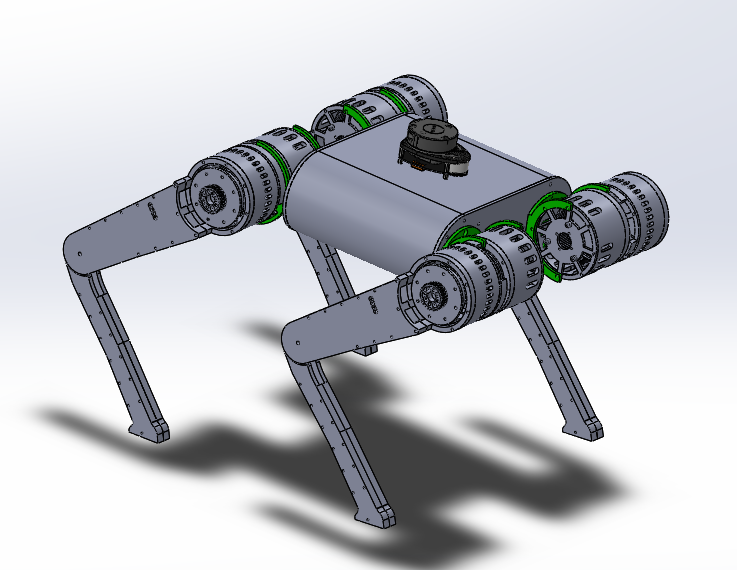
The design of the quadruped body began with having a possible 8 DOF configuration, and a 12 DOF later on. The legs are located at the upper portion of the quadruped to reduce the weight at the end of each leg as this can hinder the performance of the quadruped. To achieve this the lower leg was built using a belt and pulley located at the end of the actuator and the start of the lower leg.
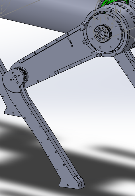
The leg was 3D printed using PETG and a metal pulley at each end. It was chosen to use a metal pulley to decrease the amount of backlash that could be caused by using this system. Below we can see a test of leg working at a set position.
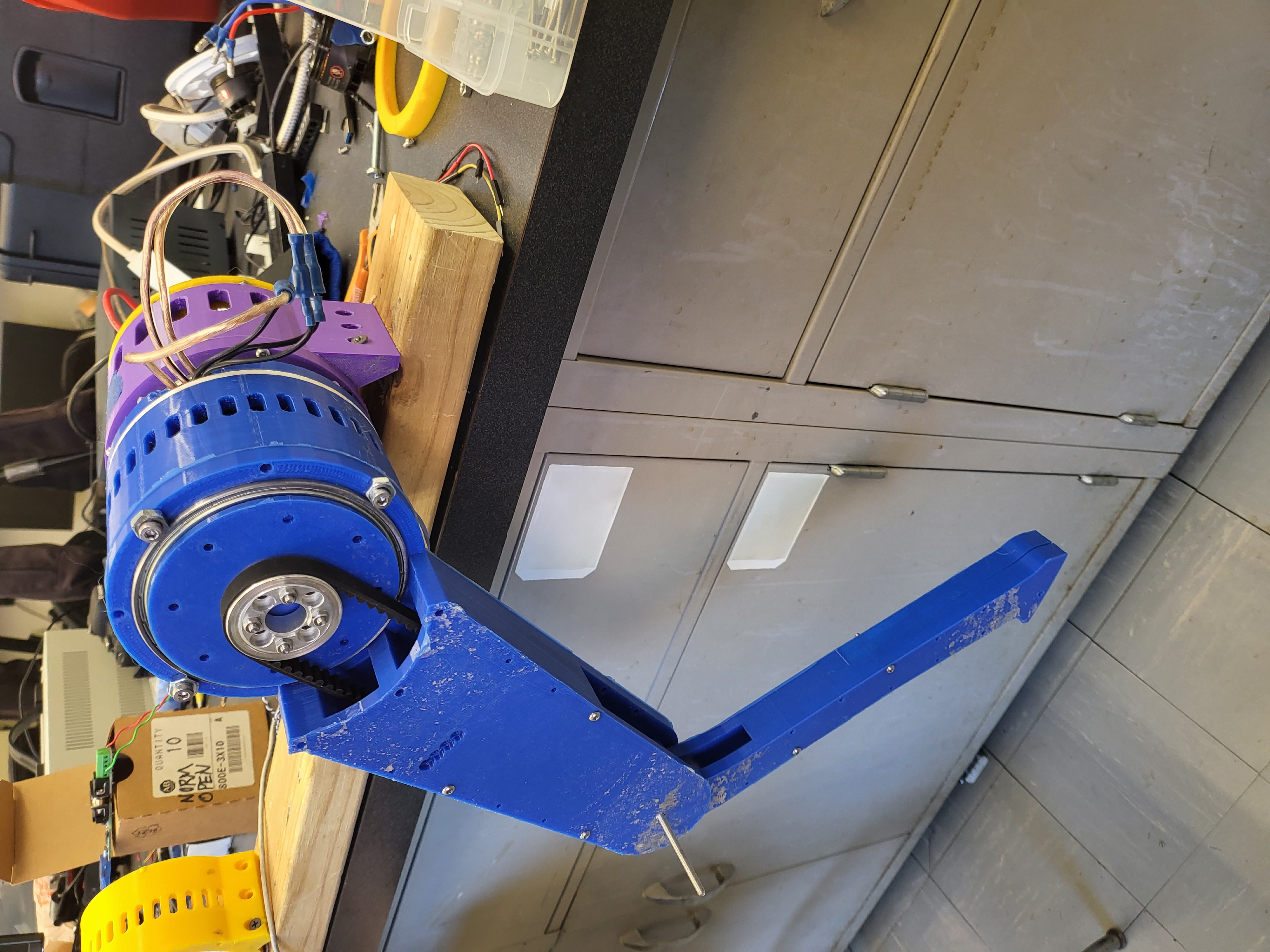
Having success with the motion of the leg it was time to test the leg to see if it could hold itself and move. The station was from a repurposed camera holder. Using the bracket holes the back of the actuator was screwed onto it. Below is a test of the leg at the station, from the video it can be seen that the leg can hold itself and even when external forces. At a later time, it was tested that the limit of the amount of force it could sustain itself was of 1kg.
Seeing the leg station was a success, we moved on to the hardware interface between the actuators and the champ motion software. Incorporating the commands through CAN highlighted in the Python library, a C++ code was developed to control the actuators similarly. The goal for this new control algorithm was to speed up the commands being processed by the Python library and also for the ease of incorporation into the champ motion software. After further testing and debugging a possible code was developed as shown below where it is shown that a specific motor is selected and spun at a specific position without each interrupting the other.
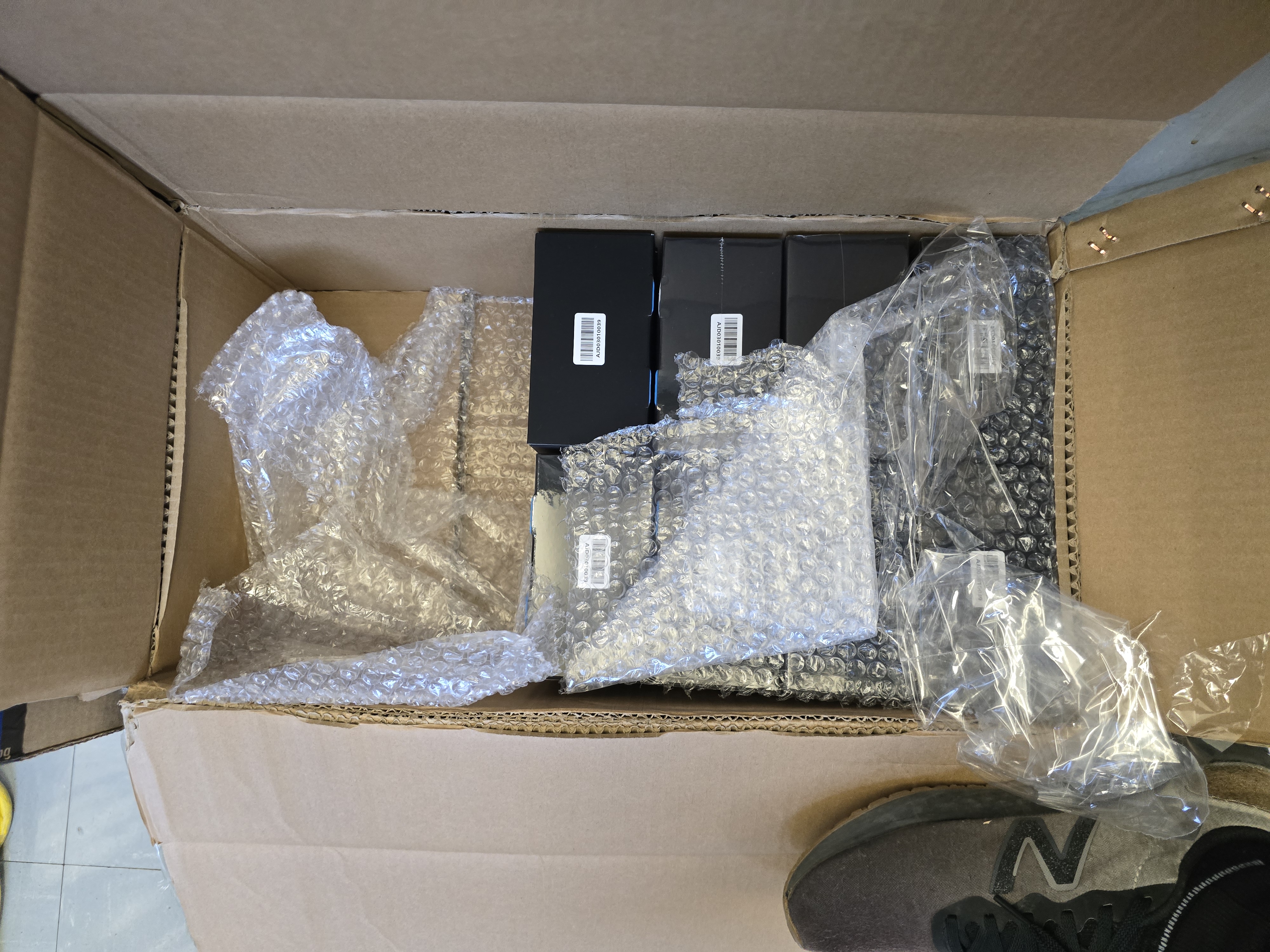
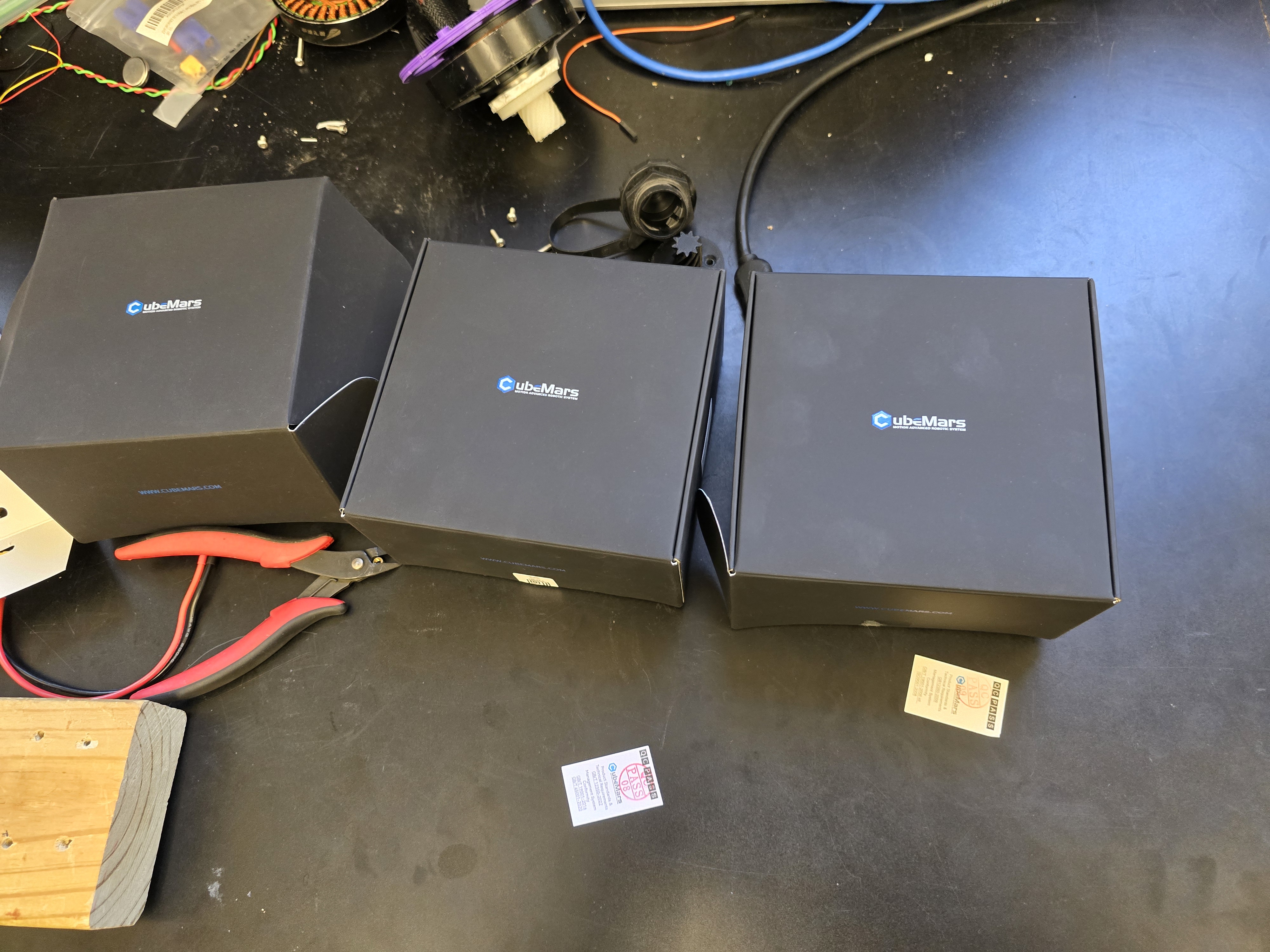
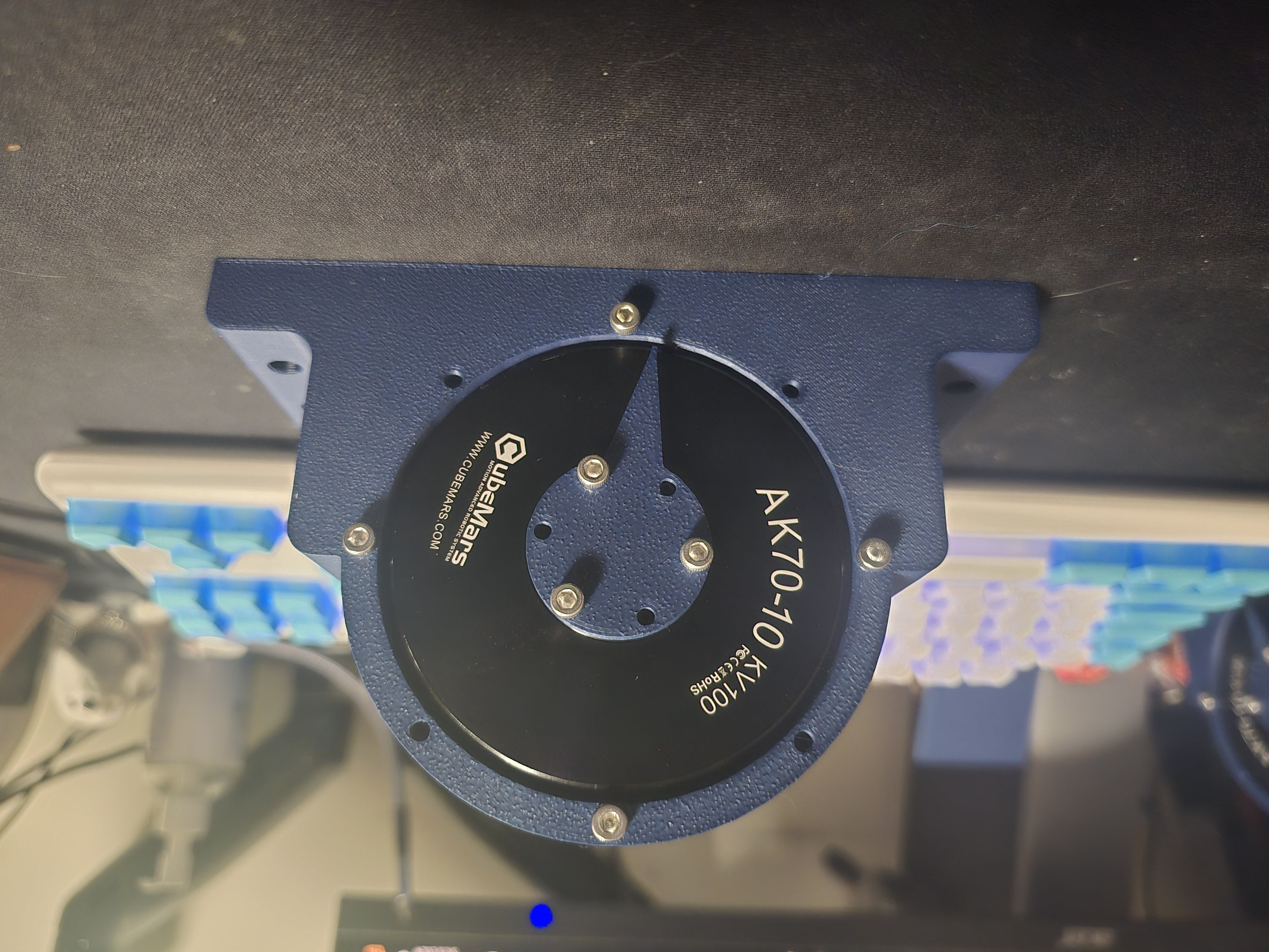
After further consideration of the backlash and the cost of building a 3D-printed actuator, we took the opportunity to buy already-made actuators with complete gearboxes from Cubemars and some with a different but similar controller board to the ones previously purchased. We recently received them in the middle of March and are now building the testing stations to test them for the amount of torque they can produce and the accuracy of position.
We found out about ICRA and their quadruped challenge on May 13-18 2024. The registration began and started working on their 3D challenge maps from 2023 with our current setup and Champ motion algorithm.

We begun the process of incorporation the motion algorithm with the ICRA map using some older models of other quadruped, the testing was begun and the incorporation of CHAMP begun.


We were successful and the robot was able to walk inside the given terrain as well as register as the "Minnesota Scouts" However, unfortunately, due to the lack of a physical commercial robot (Unitree Go1, Spot or Anymal) we were unable to go further in the tournament as we would've needed for our project robot to be already build and send to ICRA in Japan for testing the motion algorithm through the challenge map. We plan to participate next year as the robot will be fully build and will have our simulation model to test in their simulated challenges.
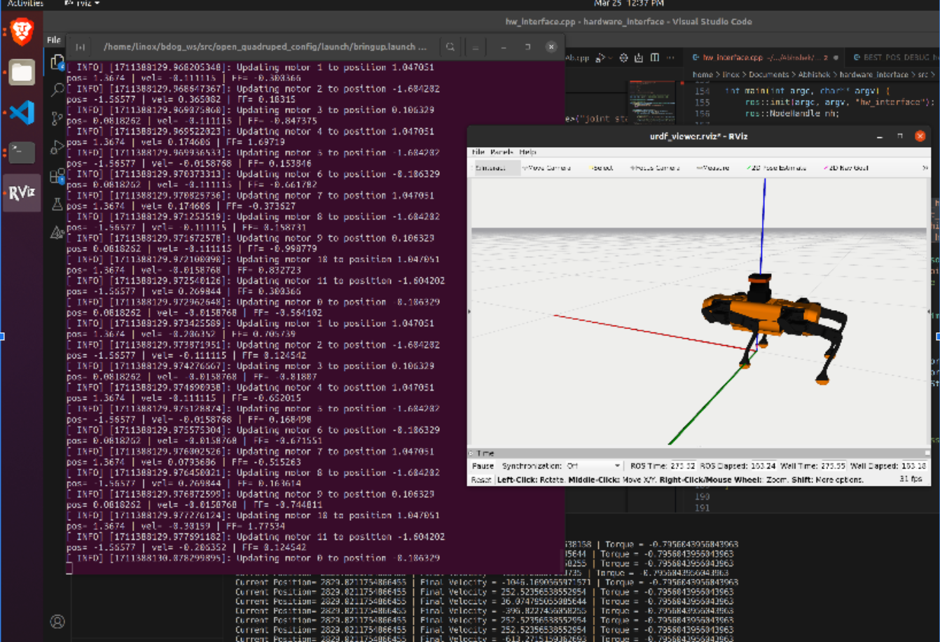
Continuing our tests, the process of controlling and enabling one leg with a champ was a challenge on its own. The main hurdle for the project was to get the hardware interface to connect with the champ positions commands being send through ROS.
Fortunately, after further developing the hardware interface algorithm, we connected the champ position commands by subscribing to the joint_states publisher in the hardware interface file. To not add more variables to the equation as well as to not damage the new motors we began testing on the old motors with the v1 controller boards. Due to the discrepancy of encoder magnet information the amount of radiant the v1 motor needed to travel were more than than the 10:1 configuration of the new motors.
The motors were able to hold their torque once they reached their given position values.
Running the single motor can be seen to update the overall quadruped simulation model on Rviz, this is further explored when the model emits a motion in real time with the motor motion.

With one motor working, it was time to start and further test the CAN bus communication systems with multiple motors.
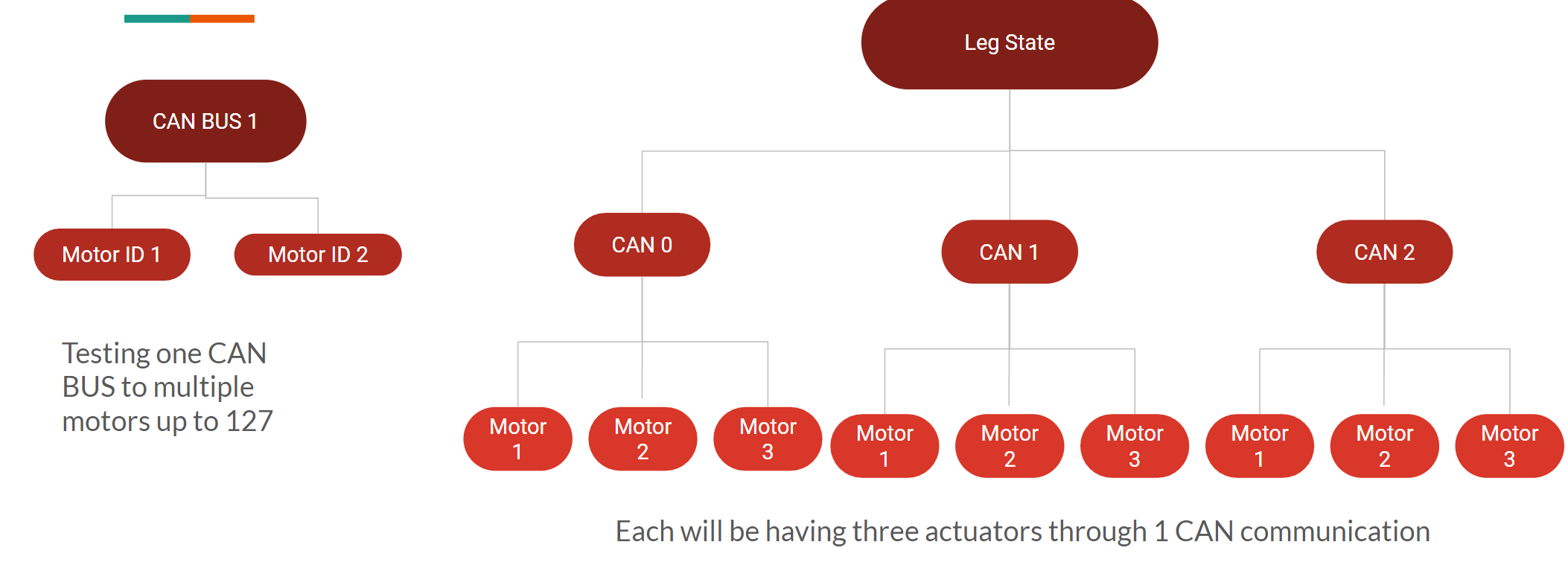
For the project there needed to be a choice between choosing from 1 can bus communicator connected to 12 motors or multiple can bus communicator with a set of motors. After further testing 1 can bus communication with 6 motors, it was found the amount of CAN messages that were sent to and from the CAN bus were too much for the single CAN bus to handle. The amount of CAN messages caused for the leg motors to receive them at a lower speed and caused for the motors to receive incorrect messages. To avoid these issues, it was decided for each leg, 3 motors, to be connected to a separate CAN bus module. The amount of CAN messages were adequate making the motors responsive and with no wrong messages.
With the CAN communication and the motion control for the motors, it was time to update the model and make a new body with the new actuators included in the model. The model featured a belt-driven mechanism for the lower leg. The repositioning of the lower motors allows for the robot to have a less stress at the lower leg as well as to keep a consistent center of mass while in motion.

The commands tests were continued and it was found the the deciphering of the CAN commands were incorrectly set up. The issue lied in the inability to obtain the correct reading of the encoder feedback in on piece of code. With this issue it gave the inability to maintain its correct position and constantly moved to try and move to the send command position. To fix this the code was updated to decipher the correct positions updated the CAN_comm main file.
Unfortunately, in late April, we started having issues with the 9 of the motors. The issue was that the motor would get stuck at random positions and will continue to get warm as it fought to attain the desired position. The motors were tested using different parameters such as velocity or torque; with those parameters, the issue was more pronounced, and thus the warranty process started with Cubemars to advise us on this issue.
We did not allow this to stop us and we continue working on more testing with our current set-up. This time we decided to test a single leg with weight on top of it. We had a couple of batteries laid on top of the leg and tested for flexion.
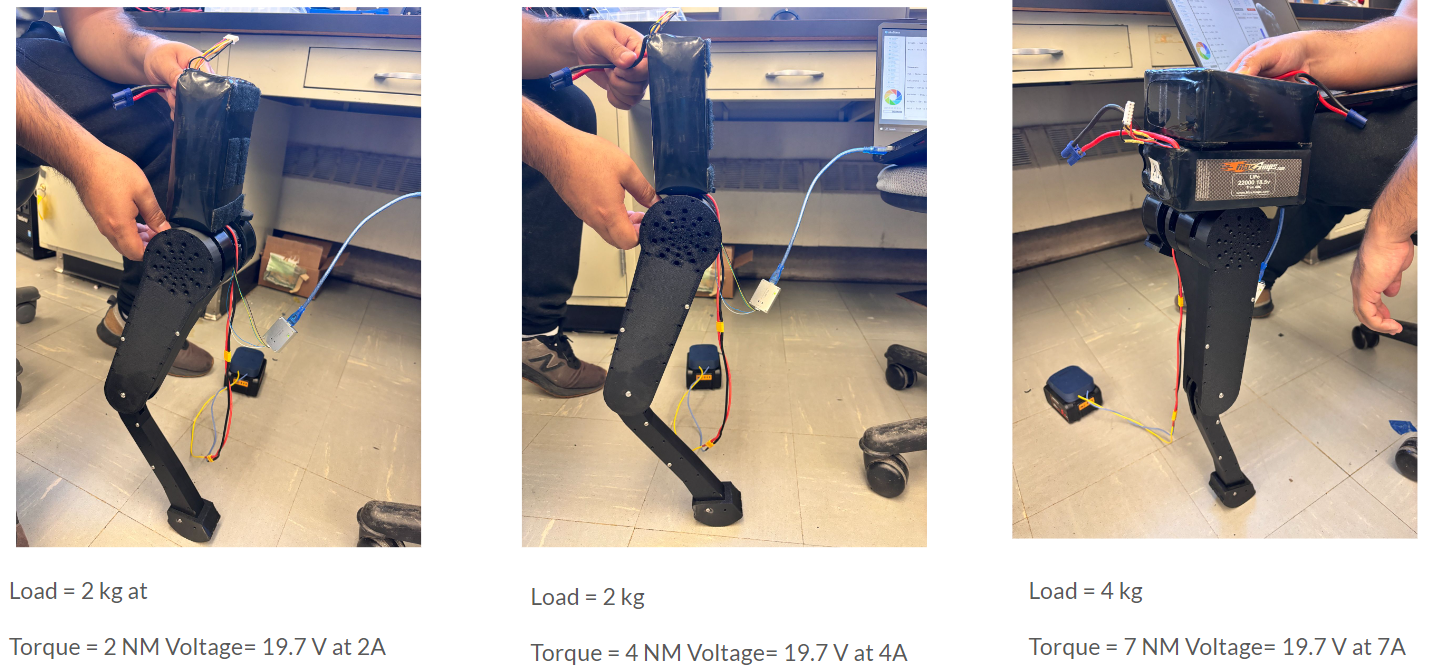
Each battery weighs approximately about 2kg, and the legs were able to handle this much holding weight without any issues. The torque values were adjusted depending on how many batteries were stacked. We stacked a maximum of two batteries for this time.
The URDF for the quadruped got updated and uploaded to the CHAMP software. Now, with this online we can simulate motion and create custom joint planning that will be created specifically for our robot as well as modify it to to different heights and modify different parameters for a better walking motion.
For further tuning and to extract the values needed to start studying the motion of the quadruped. A Python file was created so that we can visualize the position of each motor in real time. Using this file we were able to determine the direction as well as the maximum/minimum values of the motors.