Published on 2023-08-30 by ceyang
Constructing the Quadruped
During this time the quadruped platform boomed as many different iterations and designs were being made. For our project, we prioritized a lightweight, medium-sized robot body model. We adopted a design by a CAD designer of the name "KDY0523", who was inspired by Boston Dynamics' "Spot" and made a smaller version of named “Spot Micro”.
Materials & Components:
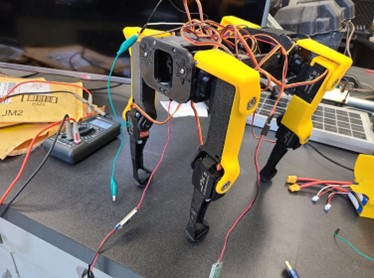
Body: 3D printed with PETG filament, material was chosen for its superior durability and UV resistance compared to traditional PLA filament.
Soles: 3D printed from TPU flexible filament for an enhanced surface grip.
Motors: Originally designed with 12 MG993 servo motors for a 12 DOF, we upgraded to stronger servos for enhanced torque.
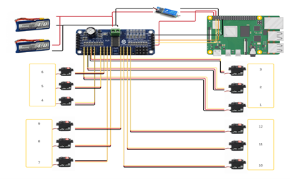
Control System: A PCA9685 I2C bus controller connected the servos, with a Raspberry Pi 3B+ serving as the main control unit. The Pi ran Ubuntu 16.04 with Kinetic ROS, leveraging libraries from GitHub user mike4192's /spotMicro repository. This setup allowed for two distinct gaits: trotting and walking.
Upgrades:
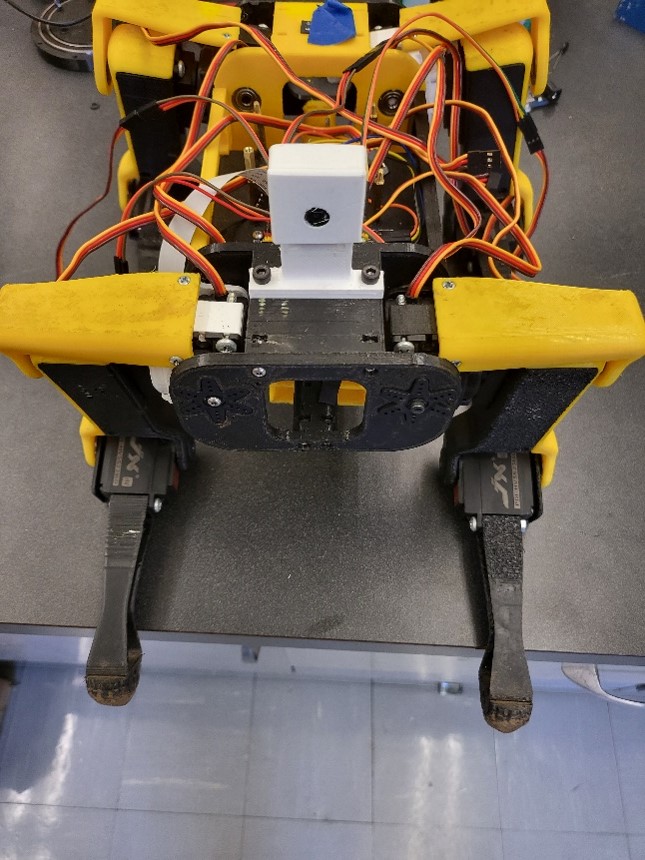
Camera: A Raspberry Pi camera was affixed at the front of the quadruped for live imaging.
Reinforced Shoulder: This enhancement merged the hip and upper arm links, reducing stress on the hip servo.
Battery Tray: Designed to accommodate two batteries, extending the robot's operational range.
Calibration Process
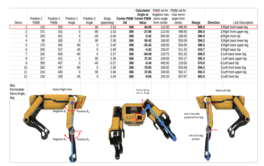
Calibrating the quadruped initially posed challenges but became more intuitive over time. Understanding the servo's 270-degree range of motion was a great factor for this. We employed a platform setup where the robot's legs dangled freely, facilitating precise calibration using a ruler and an excel sheet. This meticulous process was repeated for all 12 servo joints.
Challenges & Solutions
Leg Movement: The robot's leg occasionally failed to lift entirely, causing it to drag. By adjusting the calibration angle by an additional 10 degrees, we resolved this.
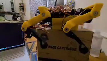
Servo Power: Field tests revealed occasional servo power deficiencies, requiring repeated motions to complete a cycle.
Conclusion
The first quadruped iteration proved that the concept of building a quadruped robot model can work on agricultural terrain. The robot can be controlled wirelessly through a Wi-Fi connection. The current build offers a stable pace at lower speeds (less than 0.26m/s). The robot at times struggled with a lack of power and moved slowly due to the servos but it continued to move overall. The camera in combination with image recognition software can be used to identify FHB in the wheat fields in real-time through a wifi connection. The concept proved to work but can be better by increasing the amount of torque generated from each leg.
References
"Spotmicro - Robot Dog By KDY0523". Thingiverse.Com, 2021, https://www.thingiverse.com/thing:3445283.
GitHub - mike4192/spotMicro: Spot Micro Quadruped Project. GitHub. (2021). Retrieved from https://github.com/mike4192/spotMicro